

In the previous article, we introduced how you can get the hardware and software needed to start learning how to code embedded systems in with an investment in hardware of under $15. In this article, we use the same hardware and review the code needed to use the buttons as well as a buzzer.
You can read the previous article in this series on embedded programming in C by visiting getting started with embedded programming for under 15 dollars.
If you are using the EEEEE UNO R3 starter kit board, which was available from Amazon for less than $15, then you have all the hardware you need. If you are using different hardware, the code shown here should work, provided your hardware is compatible with Arduino. You should only need to adjust the code to reflect where your buttons and buzzer are connected (the pin settings). The value of the EEEEE board is that it comes with hardware built-in making it perfect for learning:
The kit is actually two boards that can be connected together. A set of @@@s are included with the boards to help avoid shorting out the board when they are connected. With the board connected, as shown in the above image, you are ready to code the buttons and the buzzer. The process of coding the buttons and buzzer is similar to coding the LED lights mentioned in the previous article. You’ll need to first associate the sensor or hardware item to the pin that connects it to the board in the startup() function; then, you’ll either read or write to the sensors and widgets in the loop() function.
With a button, you’ll want to know if it has been pressed. As such, when we initialize the button pin in the setup() function, and we’ll indicate it is for input. More specifically, it will initialize it to INPUT_PULLUP, which will indicate that the button has been pushed. If our button is on pin A1, then the initialization code would be:
pinMode( A1, INPUT_PULLUP);
With the pin for the button initialized in our main code loop, we will want to check to see if the button has been pressed. This can be done by reading the pin where the button is connected, in this case, A1. Using the digitalRead() function with the button’s pin as the parameter. If this equals 0, then our button has been pressed:
If( digitalRead(A1) == 0 ) // if pressed….
That’s all that is needed!
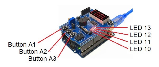
Note that on the EEEEE Uno 3 board, the three buttons are on pins A1, A2, and A3. Also, note that on the added shield board, there are four additional LEDs that are on pins 10, 11, 12, and 13. Using the code from the previous article, we now have all the pieces to write the code to light a different LED-based on which button is pressed:
void setup()
{
  // initialize our buttons
  pinMode(A1, INPUT_PULLUP);
  pinMode(A2, INPUT_PULLUP);
  pinMode(A3, INPUT_PULLUP);

  // initialize our lights
  pinMode(13, OUTPUT);
  pinMode(12, OUTPUT);
  pinMode(11, OUTPUT);
}

void loop()
{
  // make sure lights are off...
  digitalWrite(11, HIGH);
  digitalWrite(12, HIGH);
  digitalWrite(13, HIGH);

  // Check first button for press:
  if (digitalRead(A1) == 0)
  {
      digitalWrite(13, LOW);
  }

  // Check second button for press
  if (digitalRead(A2) == 0)
  {
      digitalWrite(12, LOW);
  }

  // Check third button for press:
  if (digitalRead(A3) == LOW)
  {
      digitalWrite(11, LOW);
  }
}
This code starts by setting up the three buttons on A1, A2, and A3 to be used for INPUT_PULLUP. This means we’ll be able to capture if the buttons have been pressed. We then initialize the three LEDs that we will be using. These are set for OUTPUT because we will be sending to the LEDs from our program. That’s all we need to do in our setup() function.
In the main loop() function, we start by making sure the three LEDs are off by doing a digitalWrite() to each. Within the code, we then do a simple check using an if statement to determine if the button has been pressed. If pressed, we call digitalWrite() to turn on the LED, just as we learned in the previous article.
Because the code operates in a loop, as long as a button is held down, the corresponding LED will light. Note that if you push more than one button, then the corresponding LEDs will all light.
Flashing Lights on Embedded Objects with C
You can adjust this code to make the LEDs flash when a button is pressed. This is be done by turning the light on for a fraction of a second, followed by turning the light off, and then pausing for a fraction of a second:
digitalWrite(ThisOne, LOW);
delay(50);
digitalWrite(ThisOne, HIGH);
delay(50);
Adding these additional three lines to the body of the if statements causes the corresponding light to flash instead of staying steadily on when the button is held down. If you refactor the code to put this code into its own function called blinkOne(), then your new listing would be:
void setup()
{
  // initialize our buttons
  pinMode(A1, INPUT_PULLUP);
  pinMode(A2, INPUT_PULLUP);
  pinMode(A3, INPUT_PULLUP);

  // initialize our lights
  pinMode(13, OUTPUT);
  pinMode(12, OUTPUT);
  pinMode(11, OUTPUT);
}

void loop()
{
  // make sure lights are off...
  digitalWrite(11, HIGH);
  digitalWrite(12, HIGH);
  digitalWrite(13, HIGH);

  // Check first button for press:
  if (digitalRead(A1) == 0)
  {
       blinkOne(13);
  }

  // Check second button for press
  if (digitalRead(A2) == 0)
  {
       blinkOne(12);
  }

  // Check third button for press:
  if (digitalRead(A3) == LOW)
  {
       blinkOne(11);
  }
}

void blinkOne( int ThisOne )
{
   digitalWrite(ThisOne, LOW);
   delay(50);
   digitalWrite(ThisOne, HIGH);
   delay(50);
}
Note that you can adjust the delay parameters to change the speed of the flashing.
Coding the Buzzer Instead of LEDs
The EEEEE Uno 3 board also comes with a buzzer widget on pin 3 of the secondary shield board. The code for using the buzzer is just like that for using the LEDs. You first initialize the buzzer for output, then you turn it on and off by using digitalWrite() to send a value of LOW or HIGH to the pin. The following code will turn on the buzzer that is located on pin 3 of an Arduino compatible board. Note that we defined a constant called buzzer with the pin value to make the code more readable:
#define buzzer 3

void setup()
{
 pinMode(buzzer,OUTPUT);
}

void loop()
{
   digitalWrite(buzzer, LOW);
}
When you upload this code to your board, the buzzer is going to screech until you power it off or upload a different listing! (You can change the value of LOW to HIGH and reupload the listing to shut it off as well.)
You can connect the buzzer tone to a button the same way you connected an LED:
#define buzzer 3
#define buttonA A1

void setup()
{
  pinMode(buttonA, INPUT_PULLUP); // connect Button on A1
  pinMode(buzzer,OUTPUT);    // connect Buzzer
}

void loop()
{
  digitalWrite(buzzer,HIGH); // turn off buzzer

  if (digitalRead(buttonA) == 0)
  {
      // turn on buzzer
      digitalWrite(buzzer,LOW);
      // give buzzer time to sound
      delay(1);
  }
}
With this listing, the buzzer now only screeches when you have the corresponding button pressed. There is nothing new in this listing; however, there is one line that might raise a question. You can see that after we turn on the buzzer, we delay for about 1/1000th of a second. If you don’t do the delay, then the loop is so fast that it the buzzer gets turned off immediately after it is turned on, so it isn’t heard. The delay helps ensure the buzzer is heard while the button is pressed.
Changing Buzzer Frequencies
You can manipulate the frequency of the buzzer by varying the amount of time it is on versus the amount of time it is off. For example, if you turn the buzzer on for 5 ms and then off for 2 ms, it will sound different than if you turn it on for 30 ms and then off for 2 ms. The following listing adds code for all three buttons. With each button, a different amount of time is set for the buzzer to be on, followed by a delay. You’ll see that the tone is now different when you press each of the three buttons:
#define buttonA A1
#define buttonB A2
#define buttonC A3
#define buzzer 3

void setup()
{
 pinMode(buzzer,OUTPUT);
 pinMode(buttonA, INPUT_PULLUP);
 pinMode(buttonB, INPUT_PULLUP);
 pinMode(buttonC, INPUT_PULLUP);
}

void loop()
{
  unsigned char i;
  digitalWrite(buzzer,HIGH);
  if (digitalRead(buttonA) == 0)
  {
    //output an frequency
    for(i=0;i<80;i++)
    {
      digitalWrite(buzzer,HIGH);
      delay(1);//wait for 1ms
      digitalWrite(buzzer,LOW);
      delay(1);//wait for 1ms
    }
  }
  if (digitalRead(buttonB) == 0)
  {
    //output an frequency
    for(i=0;i<30;i++)
    {
      digitalWrite(buzzer,HIGH);
      delay(5);//wait for 5ms
      digitalWrite(buzzer,LOW);
      delay(2);//wait for 2ms
    }
  }
  if (digitalRead(buttonC) == 0)
  {
    //output an frequency
    for(i=0;i<10;i++)
    {
      digitalWrite(buzzer,HIGH);
      delay(30);//wait for 30ms
      digitalWrite(buzzer,LOW);
      delay(2);//wait for 2ms
    }
  }
}
You can change the delay and run the listing to determine which tones you like.
More Cheap Embedded Programming Thoughts
For under $15, you’ve now had a chance to learn to code LEDs, buttons, and buzzers. The code you’ve seen should work on any Arduino compatible board as long as you wire the appropriate controls and adjust the code to the pin numbers you use. As you can see, it takes very little code to activate the widgets and sensors.
It is worth noting that there are libraries that you can use to gain more control over the widgets and sensors. With more control comes more code. The focus of this article, however, was to show you how quickly, easily, and cheaply you could get started.