

- System Call Optimization with the SYSENTER Instruction
- Why Is SYSENTER Faster?
- SYSENTER or SYSCALL?
- How Does a System Call via the SYSENTER Instruction Work?
- The Mechanics of SYSENTER
- The Mechanics of SYSEXIT
- SYSENTER or ‘int 2e’?
- Are There Different Operating System Binaries for SYSENTER and ‘int 2e’?
- KiFastCallEntry Reuses the Good Old KiSystemService Function
System Call Optimization with the SYSENTER Instruction
My previous article, “How Do Windows NT System Calls REALLY Work?”, explains how Windows NT calls system services by using an ‘int 2e’ software interrupt. Newer platforms, such as Windows XP and 2003, normally use another method to call system services. As explained in my previous article, the ‘int 2e’ instruction uses both an interrupt gate and a code segment descriptor to find the interrupt service routine (KiSystemService) that services the ‘int 2e’ software interrupt. Because the CPU will have to load one interrupt gate and one segment descriptor from memory to know what interrupt service routine to call, significant overhead is involved in making an ‘int 2e’ system call. The SYSENTER instruction drastically reduces this overhead.
By John Gulbrandsen 9/16/2004
John.Gulbrandsen@SummitSoftConsulting.com
Why Is SYSENTER Faster?
As explained in my previous article, the interrupt gate (entry 2e in the Interrupt Descriptor Table) identifies the entry in the Global Descriptor Table which in turn identifies the code segment that contains the KiSystemService function. Loading the 8-byte interrupt gate and segment descriptors from memory is sped up by keeping these gate/descriptors cached in the processors on-chip (level 1) or off-chip (level 2) cache. The CPU is very likely to find these gate/descriptors cached because each and every Windows NT system call uses the same interrupt gate and code segment descriptor when making a system call via the ‘int 2e’ software interrupt. However, the CPU still must perform memory read cycles to read from the cache, make access privilege checks, and so forth every time when switching the privilege level via the ‘int 2e’ software interrupt. After having analyzed the whole sequence of events involved in switching to kernel-mode, it is clear that it would be much faster if the CPU could be hard coded to always switch to the same location in a kernel-mode segment when a system call is issued. Because the destination function is now hard coded, no memory reads are necessary to find out where the system call should end up. This would speed up system calls significantly. This is exactly what is being done by the Intel SYSENTER and the AMD SYSCALL instructions that are present in the Pentium II, AMD K7, and newer CPUs. These instructions are collectively referred to as “Fast System Call” instructions.
SYSENTER or SYSCALL?
Why are there two different instructions to make a fast system call? Most likely, Intel and AMD simultaneously and independently developed their versions of the Fast System Call instructions. They are both functionally identical, but they use somewhat different configuration registers in the CPU to set up the destination segment and the offset within the destination segment where the system call function resides. Because they are both so similar, I willmainly describe the SYSENTER version and point out differences where they matter.
How Does a System Call via the SYSENTER Instruction Work?
As was explained above, the SYSENTER call uses hard-coded code segment descriptors to describe the target code segment. Instead of setting up the CPU accordingly to a specification in memory described by a code segment descriptor (segment base, segment size, segment privilege level, and so on), the CPU always sets up the target segments base to 0, its size to 4GB, and its privilege level to 0 (kernel-mode). What is NOT hard-coded is the exact target location within the target segment; in other words, the address of the function being called in the kernel mode code segment. This function is called ‘KiFastCallEntry’ in Windows XP and newer platforms. So, if the address of the KiFastCallEntry function is not hard-coded, how does the CPU know where to jump after switching to the target code segment? The answer is that the CPU uses the “Model Specific Registers” (MSR). MSRs are configuration registers that are used only by the operating system; application programs never use them. The content of the MSRs define how the CPU will behave. The RDMSR (Read MSR) and WRMSR (Write MSR) instructions are used to modify the MSRs.
The CPU is using an MSR called SYSENTER_EIP_MSR to know where to jump when the SYSENTER instruction is executed. In other words, the SYSENTER_EIP_MSR register contains the address of the KiFastCallEntry function. This MSR must be set up by the operating system very early in the boot process for system calls via the SYSENTER instruction to work. As explained in my previous article, the operating system switches to the kernel-mode stack when an operating system call is made. This behavior must be the same when making a SYSENTER call or else the stability of the system will be compromised (the whole point of switching to a kernel-mode stack is to assure that the integrity of the stack used in kernel-mode can be trusted). So, how does the CPU switch to the kernel-mode stack? Again, it uses Model Specific Registers. Like the Code Segment, the Stack Segment is loaded with hard-coded values when the CPU executes a SYSENTER instruction. It is loaded with exactly the same values that a system call via an ‘int 2e’ instruction would result in; in other words, a flat model where the base is 0 and the size is 4GB. Like the EIP, the ESP is not hard-coded. Its value is taken from the SYSENTER_ESP_MSR that is also set up by the operating system at boot time.
The Mechanics of SYSENTER
All Model Specific Registers are 64-bit registers. They are loaded from EDX:EAX using the WRMSR instruction. The MSR index in the ECX register tells the WRMSR instruction which MSR to load. The RDMSR register works the same way, but it stores the current value of an MSR into EDX:EAX. The Programming manual for the CPU used specifies what index to use for any given MSR. Table 1 lists the MSRs used by the SYSENTER/SYSEXIT instructions.
| Model Specific Register name | Index | Usage |
| SYSENTER_CS_MSR | 174h | CS Selector of the target segment |
| SYSENTER_ESP_MSR | 175h | Target ESP |
| SYSENTER_EIP_MSR | 176h | Target EIP |
Table 1. The Model Specific Registers used by the SYSENTER instruction.
Note that SYSENTER_CS_MSR contains the Code Segment Selector of the target code segment (the segment that contains the KiFastCallEntry function). This value is loaded into the visible part of the CS register but it is in fact never used by the SYSENTER or SYSEXIT instructions! Remember that all information related to the target code segment is hard-coded by the SYSENTER instruction and that therefore the Segment Selector loaded into CS is not used to find the target code segment in the GDT like in the case of the ‘int 2e’ method of making system calls. To keep consistency between the value in the CS Segment Register and the Descriptor it points to, the operating system must however set up a real Code Segment Descriptor in GDT. In fact, the operating system must set up four Segment Descriptors in the Global Descriptor Table to keep consistency between the Segment Registers and the content in the GDT. Intel specifies that these GDT descriptors must reside contiguously in the GDT. Figure 1 illustrates this.
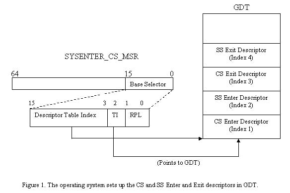
As Figure 1 shows, the operating system sets up four segment descriptors in the GDT. The “CS Enter Descriptor” at index 1 in the GDT describes the kernel-mode code segment that contains the KiFastCallEntry routine. The “SS Enter Descriptor” describes the kernel-mode stack segment that will be switched to when calling into kernel-mode via a SYSENTER instruction. The “CS Exit Descriptor” and “SS Exit Descriptor” are used when switching back from kernel-mode to user-mode via the SYSEXIT instruction. The details involved in switching back into user-mode will be covered in detailed later in this article.
To summarize, the steps taken when executing the SYSENTER instructions are:
- The CPU loads the Segment Selector in the SYSENTER_CS_MSR into the visible part of the CS register.
- The hidden part of the CS register is loaded with hard-coded values like previously described.
The SS register is loaded with a segment selector that points to the entry in the GDT after the CS Enter Descriptor; in other words, to the SS Enter Descriptor. Because the SYSENTER_CS_MSR (and also the CS register) contains the binary value 00001000 or hexadecimal 0x08, the SS will be loaded with a binary value of 00010000 or hexadecimal 0x10. The Intel Programmer’s manual simply says that “the SS register is set to the sum of 8 plus the value in SYSENTER_CS_MSR” which results in a segment selector with an index one higher than the segment selector in SYSENTER_CS_MSR.
- The hidden part of the SS register is loaded with hard-coded values as previously described.
The EIP register is loaded from the SYSENTER_EIP_MSR and the CPU starts executing code in kernel-mode (KiFastCallEntry).
The Mechanics of SYSEXIT
The SYSEXIT instruction is very similar to the SYSENTER instruction with the main difference that the hidden part of the CS Register is now set to a priority of 3 (user-mode) instead of 0 (kernel-mode). As shown in Figure 1, the GDT contains the CS Exit Descriptor and SS Exit Descriptors at index 3 and 4. As in the case of the SYSENTER instruction, the CS and SS Exit Descriptors are not used at all by the SYSEXIT instruction. These descriptors are only there to create consistency between the selectors selected into the CS and SS registers and the corresponding CS and SS Exit Descriptors when returning to user-mode. The selectors loaded into the CS and SS Registers by the SYSEXIT instruction correctly points to the unused Exit CS and SS Descriptors in the GDT. These selectors are:
| Selector (binary and hexadecimal) | Usage |
| 00011000b = 18h | Points to the CS Exit Descriptor (Index 3 in GDT) |
| 00100000b = 20h | Points to the SS Exit Descriptor (Index 4 in GDT) |
Table 2. The CS and SS Exit Selectors used by the SYSEXIT instruction.
As in the case of loading the SS selector during the SYSENTER instruction, the SYSEXIT instruction loads the CS and SS with descriptors that have indices into the GDT 2 and 3 higher than the index in the segment selector in the SYSENTER_CS_MSR register.
If you have paid close attention so far, you might have noticed that there is no “SYSEXIT_EIP_MSR” or “SYSEXIT_ESP_MSR” register. So, how does the SYSEXIT instruction know where to return to in the user-mode code that initially called SYSENTER? When you think about it, such information could not be fixed in an MSR because each system call can potentially originate from completely different locations in user-mode. Therefore, it is the responsibility of the caller (the code that calls SYSENTER) to place the address the CPU is to return to after the system call has returned in the EDX register. The caller must also place the current stack pointer (the value of ESP) in the ECX register. The SYSEXIT instruction will then restore the original value in the EIP and ESP by copying the content from EDX and ECX respectively. This will cause the execution to continue at the instruction after the original SYSENTER instruction.
SYSENTER or ‘int 2e’?
How does the operating system (XP or newer) know whether it should use the new SYSENTER instruction when calling a kernel-mode function? The answer is that the operating system queries the CPU to find out whether the SYSENTER instruction is supported via the CPUID instruction. If the SEP (SysEnter Present) bit is set, the operating system will use the SYSENTER instruction instead of ‘int 2e’. This information is cached by the operating system so that once it has been determined that SYSENTER is supported it will always be used instead of ‘int 2e’. The same is true for the AMD CPUs SYSCALL instruction.
Are There Different Operating System Binaries for SYSENTER and ‘int 2e’?
As described in my previous article, the NTDLL.dll system call stub DLL is responsible for calling the ‘int 2e’ instruction whenever calls into the kernel were made on Windows NT (Windows 2000 and older, not including Windows 9x, which has a completely different architecture). Because Windows XP now has three different ways to call a kernel-mode function, will the operating system have to check which method to use before each and every system call? The answer is no. Instead, it calls a special page of memory that is mapped into all processes, called the “SharedUserData” page, which contains a function called “SystemCallStub”. NTDLL calls the SystemCallStub for each system call. Because the SystemCallStub calls a kernel-mode function differently depending on whether SYSENTER, SYSCALL, or ‘int 2e’ is used, the operating system binaries are identical regardless of the capabilities of the CPU.
KiFastCallEntry Reuses the Good Old KiSystemService Function
KiSystemService still does all the hard work involved in the actual dispatching of the system call once kernel-mode has been reached. KiFastCallEntry simply calls the implementation of KiSystemService after first having prepared a stack image identical to one produced by an ‘int 2e’ style system call (see my previous article for the details of how KiSystemService expects the stack to be set up). The question now is: How does the KiSystemService know whether SYSEXIT, SYSRETURN, or ‘iretd’ should be used to return to user-mode? For this to work, the end of the KiSystemService function has been modified to handle any of the three system call types. In fact, there are three different Exit-routines depending of what call-style was used to enter kernel-mode:
| Kernel Function Name | Call style | Exit instruction |
| KiSystemCallExit | ‘int 2e’ | iretd |
| KiSystemCallExit2 | SYSENTER | SYSEXIT |
| KiSystemCallExit3 | SYSCALL | SYSRETURN |
Table 3. The three different ways to exit a system call.
The really interested reader can disassemble these functions to see what is really going on, but this is not done in this article. The bottom line is that the choice of which of these three functions to use to return to user-mode is made in the “KiSystemServiceExit” function based on the feature-bits of the CPU (returned from the CPUID instruction).